DigiRoll
December 15, 2024
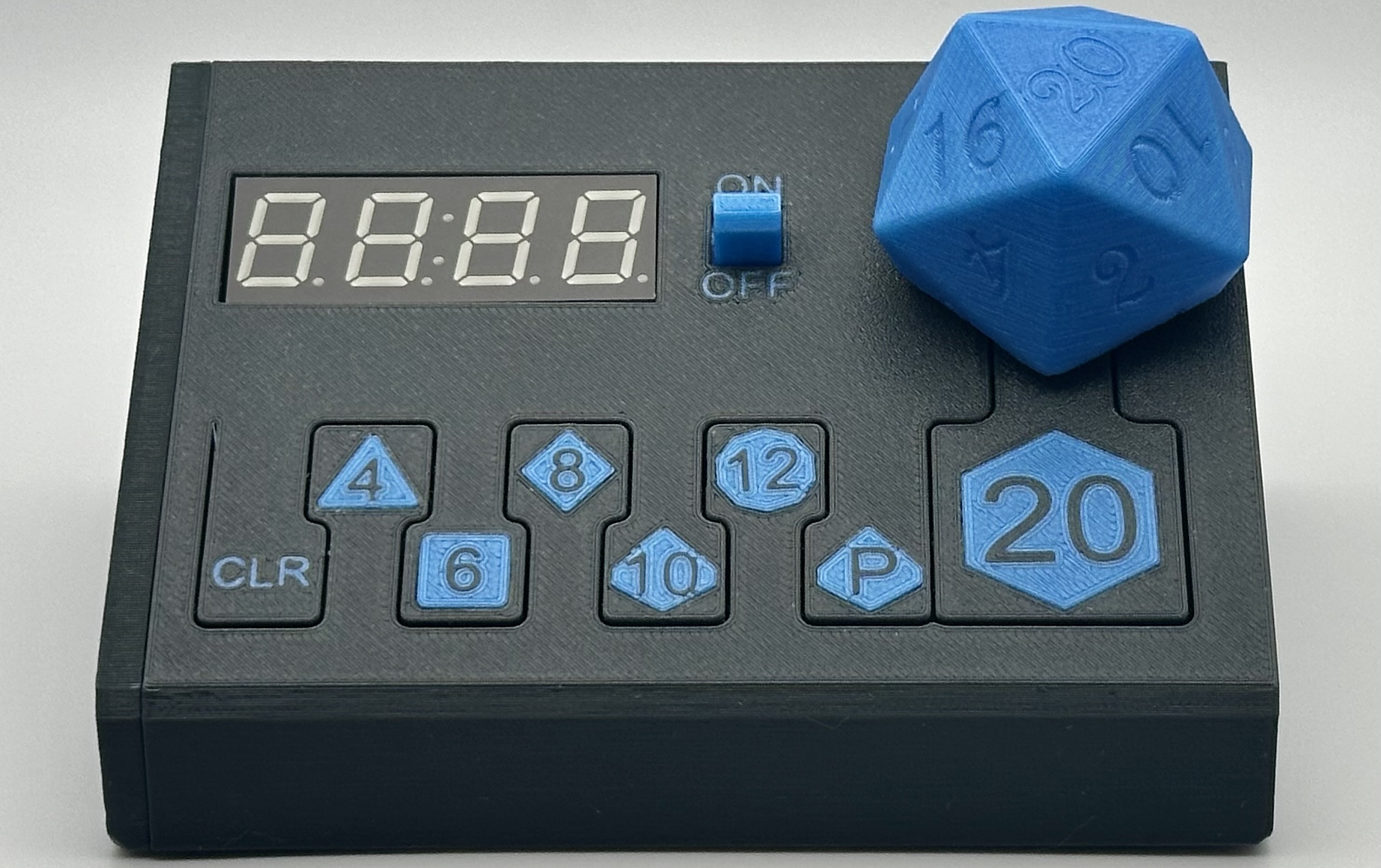
DigiRoll is a digital dice roller.
December 15, 2024
DigiRoll is a digital dice roller.
Dungeons and Dragons is one of my favorite pastimes. I love using physical dice, but that can get pretty complicated when working with a large roll. I also love using digital solutions like DnD Beyond, but it can be really distracting to have your phone or computer active while playing.
I had an idea for a device that met in the middle of physical and digital, and thus the DigiRoll was born. It allows you to roll up to 9 of each die, and shows you their individual results along with the sum.
For this project, I had a few hardware goals in mind. I wanted to design and order the printed circuit board (PCB) myself, I wanted to do much of the electrical engineering myself, and I wanted the end circuit to be very power efficient.
Having never designed a PCB before this project, this was an excellent opportunity to learn the entire process from design to manufacturing. I used KiCad for the PCB design and JLCPCB for fabrication. Once I created the schematic in KiCad, transitioning to the PCB layout was pretty straight forward. By watching several YouTube tutorials, I was able to learn the steps and complete the design independently.
I wanted to handle as most of the electrical engineering myself, while still keeping the project's timeline reasonable. To save on time, I made a compromise by using breakout boards for the boost converter and the 7-segment display. If I do a second revision, I plan to design these components myself, which could potentially reduce the cost per unit while also allowing me to have most of the board assembled at the factory.
The main components of the board are an ATtiny84 MCU, a CD4532 8-bit encoder, and an SN74HC595 shift register. Initially, I considered using an ATtiny85, but its limited number of pins made it impractical unless I could use I2C for all peripherals, which wasn’t feasible. The shift register controls the LEDs for the buttons, while the encoder allows the device to support eight buttons using only four MCU pins (three for encoding the value and one for interrupts).
Designing the mechanism for “spinning” the dice was the next major challenge. A Hall effect sensor was an ideal choice for this purpose, but these sensors are notoriously power-hungry, conflicting with my goal of maximizing power efficiency. To address this issue, I powered the sensor through a GPIO pin on the MCU. This approach allowed me to disable the sensor when it wasn’t needed, conserving power during most of the device’s active period.
For the display, I selected an Adafruit breakout board featuring the HT16K33 driver. I used the Adafruit_LEDBackpack library, which also simplified the integration process. However, the library didn’t include commands to put the HT16K33 into sleep mode, which was a necessary feature given its multi-milliamp power consumption. Fortunately, I was able to manually send sleep and wake instructions to the HT16K33.
The final major component was the boost converter. Although I could have integrated this into the circuit myself, my lack of experience with them and the desire to complete the project quickly led me to use another breakout board featuring the TPS61023. This allowed the device to be powered by just two AA batteries, even though the system required 5V. The efficiency of this setup is approximately 88%, which is acceptable but not optimal.
By combining these hardware choices with low-current LEDs and efficient software, I achieved a reasonable power profile. Using Nordic's Power Profiler Kit II, I analyzed the current consumption during different operating modes. At maximum current draw, the device consumes an average of roughly 60mA (see image 1 below), and in deep sleep mode, it consumes about 11µA (see image 2 below). Considering that a typical AA battery has a rough capacity of around 2,200mAh at these draw rates, this translates to approximately 70 hours of operation at maximum current draw and up to 400,000 hours (or about 45 years) in sleep mode.


The software is open source and available at github.com/zbauman3/digi-roll.
Initially, I wanted to develop the software for this project using the bare-bones avr-libc. However, since I was using a breakout board for the 7-segment display, this would have required me to write a custom library for I2C communication with the HT16K33 driver. While this was possible, it would have taken more time than I wanted to invest. Instead, I decided to use the Arduino framework for this project.
I'm not a fan of the Arduino IDE, so I tried out PlatformIO. This turned out to be an excellent choice, and I plan on using it for future projects, even though I would have preferred to work with the native AVR framework.
The project required handling multiple tasks concurrently, and I would normally reach for a real-time operating system in such cases. However, the ATtiny84 doesn’t have enough flash memory to support a full RTOS. As an alternative, I chose to use a cooperative multitasking library — AceRoutine. This lightweight library supports coroutines and, for five coroutines (effectively “threads”), it consumes only about 900 bytes of flash and 80 bytes of RAM.
For the software architecture, I used a MVC pattern. This approach allowed for a clear separation of input, state, and output logic. Controllers manage the buttons and Hall effect sensors, views handle the LEDs and 7-segment display, and a single “state” model ties everything together. Overall, this organization worked well, although some controller logic ended up in the state model. I may revisit this in a future iteration to improve the separation of concerns.
The final program occupies 6,994 bytes of flash and uses 269 bytes of RAM.


To select a die, press the button for that die. While you are choosing a die, its light will flash to indicate it is selected. Once selected, spin the large D20 spinner to roll. The light for the selected die remains lit when your result is displayed.
If you’d like to roll multiple dice of the same type (up to nine, such as 9d20), simply press the die’s button repeatedly until you reach the desired quantity. The light will flash while selecting. When you’re ready, spin the large D20 again to roll all chosen dice.
After rolling multiple dice, the currently selected die’s light will stay illuminated. Press the die’s button to cycle through the individual results. To see the total of all the dice rolled, keep pressing the button until the = sign appears. The number shown at that point is the sum of your rolls.
| Part | Description | Count | Link |
|---|---|---|---|
| ATTINY84A | Main MCU | 1 | Mouser |
| CD4532BE | 8-bit priority encoder (Buttons) | 1 | Mouser |
| SN74HC595N | Shift register (LEDs) | 1 | Mouser |
| 7-Segment Display Breakout | I2C, 4 digit display | 1 | Adafruit |
| TPS61023 Breakout | Boost converter | 1 | Adafruit |
| WP7113LVBC/D (LED) | Low current LEDs | 7 | Mouser |
| 2.4K Ohm Resistors | LED resistors | 7 | Mouser |
| Tactile Switches | 6 x 6 x 5mm buttons | 8 | Adafruit |
| 1M Ohm Resistors | Button resistors | 8 | Mouser |
| 0.1uF 50V Capacitors | Power stabilization | 2 | Mouser |
| SPDT Slide Switch | Power switch | 1 | Adafruit |
| US5881UA | Hall effect sensor | 1 | Mouser |
| Battery Holder | 2 x 1.5V AA | 1 | Amazon |
| Filament | Parts | Link |
|---|---|---|
| Prusament PETG Anthracite Grey | External case | Prusa |
| Prusament PLA Azure Blue | Buttons, power switch, and dice spinner | Prusa |
| Part | Description | Count | Link |
|---|---|---|---|
| Rubber Feet | For the bottom of the case | 4 | Amazon |
| Bearings | For the dice spinner | 2 | Amazon |
| Magnets | For the dice spinner | 1 | Amazon |
| Battery Connectors | Allows disconnecting the battery from the board for easy installation | 1 | Adafruit |
| PCB Screws | M2 x 8mm | 4 | N/A |
| Hot glue | Securing the display and the magnet holer | - | N/A |
| Tacking screws | Attaching the battery holder to the case | 2 | N/A |
| Header pins | Attaching the breakout boards and a ISP connection for programming | 14 | N/A |
The schematic and PCB were designed with KiCad.