Wattson Heirloom
March 15, 2024
A project to build a 3D-printed "Telemetry Receiver Module" for the Apex Legends character "Wattson".
March 15, 2024
A project to build a 3D-printed "Telemetry Receiver Module" for the Apex Legends character "Wattson".
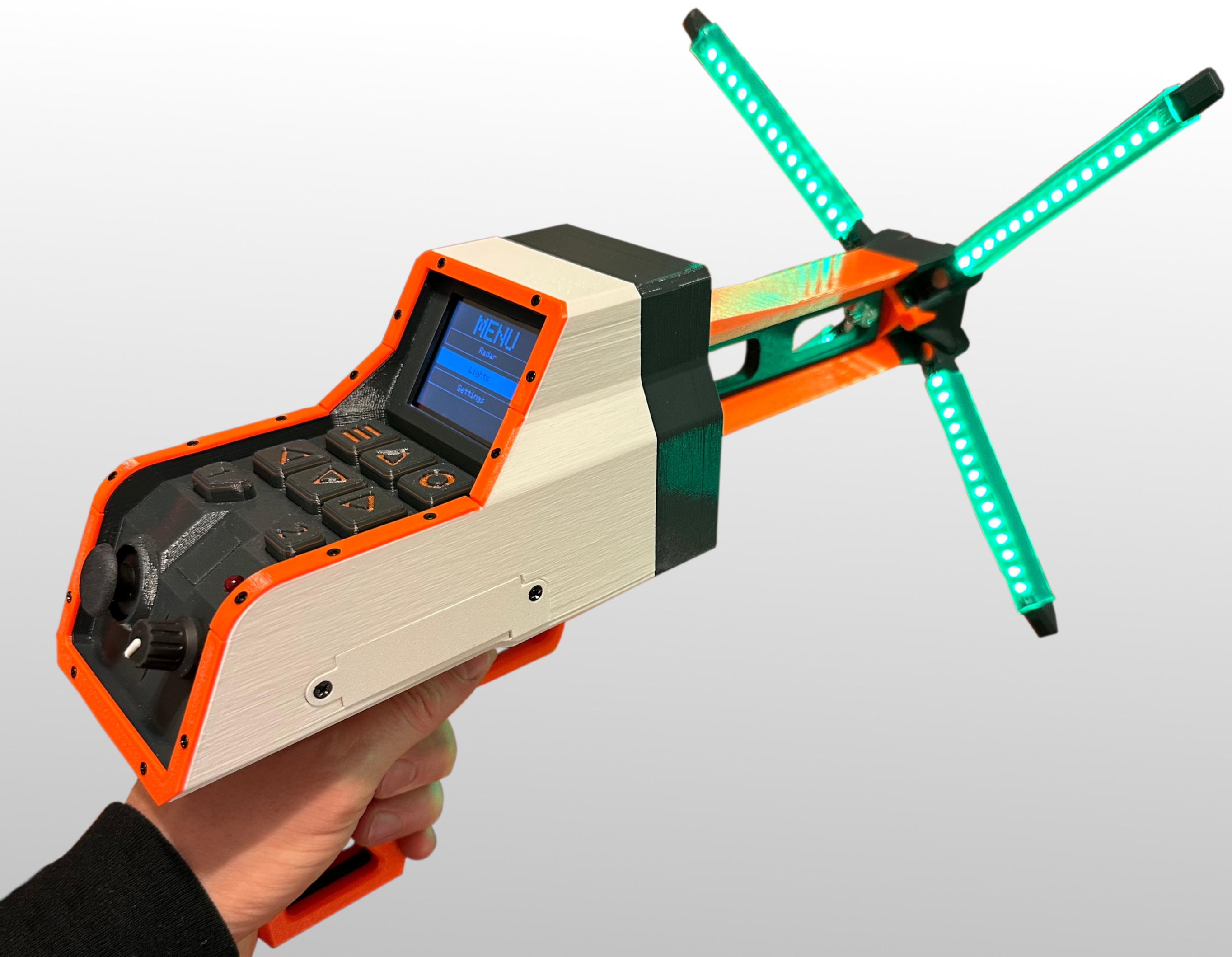
Wattson is a character from the video game Apex Legends. This project started as a simple idea: build a working version of her Heirloom for my nephew’s birthday. I didn’t want just a prop that looked right — I wanted it to work. It needed to light up, vibrate, and display data.
For the MCU, I chose an Adafruit QT Py ESP32-S2, mostly because it was small, fast, and I already had one. I wanted something capable of driving an LCD, controlling LEDs, animating NeoPixels, and handling a few sensors without overloading the CPU. It ended up being a solid choice, but if I were to do it again, I’d pick a dev board with more exposed GPIO pins. That would’ve made wiring a lot simpler and saved me from needing a GPIO expander.
Because of the limited pins, I used an MCP23017 I2C GPIO expander. Between that and the rotary encoder on an I2C breakout, I ended up juggling multiple interrupt lines that didn’t play nicely together. My first attempt was to tie both interrupt lines together into one wire. However, the expander’s line is open-drain and pulled high, while the encoder’s was actively driven – so they didn't actually work together. After a lot of debugging, I gave up and gave each device its own interrupt line.
The joystick was another unexpected headache. The analog readings weren’t stable, and the stick drifted badly around its resting point. To fix that, I added a small dead zone around the middle, averaged multiple samples for each reading, and only sampled frequently when the stick moved outside that zone. That combination made the controls feel smooth and reduced wasted CPU time from constantly reading.
For haptics, I wired a small vibration motor through a BJT so it could draw power from the 5V rail. The vibration added a ton of reality to the device, feeling the feedback in your hand just really tricks the brain.
The light rods are made up of NeoPixels, with each strip wired in parallel. That means the MCU can control the same pixel index across all strips simultaneously, but not individual strips separately.
The software is open source and available at github.com/zbauman3/wattson-heirloom.
When I started the project, I wasn’t very familiar with RTOS and didn’t want to over complicate things — especially since I was on a deadline for my nephew’s birthday. So I stuck with PlatformIO, the Arduino framework, and used a lightweight coroutine library (AceRoutine) for cooperative multitasking. It turned out to be a great learning experience. I had to think carefully about how long each coroutine ran before yielding, because if one coroutine hogged the CPU, the rest would starve. It forced me to write efficient, predictable code.
I wasn’t sure what architecture to use at first, but since I knew I’d be building a UI, I modeled it loosely after an MVC pattern. The inputs (joystick, trigger, buttons, and encoder) act as controllers. The overall system state is the model. And everything that outputs feedback (the LCD, LEDs, and vibration) are the views. It’s a structure that felt natural coming from web development, and it made adding new features much easier later on.
The UI itself is a small menu-driven system. The rotary encoder or arrow buttons navigate rectangular “buttons” drawn on the LCD. I built a base screen class that each screen could extend to define its own layout and behavior. It’s a simple system, but surprisingly flexible — each page can override how inputs behave without touching the rest of the logic.
For the radar screen, I used the wonderful Adafruit GFX Library, which gives you low-level primitives like lines, circles, rectangles, and text. That allowed me to dray a radar display with three “pings” moving across it. Each ping travels from one random point to another, animating at a random speed. When a ping enters the center circle, the device’s red status light starts blinking. The light rods also pulse in sync with the radar sweep.
The 3D modeling ended up being the hardest part of the whole build. I couldn’t find any game-accurate models that fit what I needed, so I modeled everything from scratch — the case, light rods, hinges, buttons, handle, trigger, trim, clamps, etc.
The first challenge was fitting all the hardware into a reasonable form factor without making it comically large. Once I had that figured out, I had to design a mechanism for the light rods to collapse and expand — and stay put in either position. I went with a 45-degree rotating joint held in place with embedded magnets (see the video below). The wires run cleanly through the inside of the joint, and the magnets lock it into place when folded or extended. That mechanism alone took around a dozen test prints to perfect.


| Part | Description | Link |
|---|---|---|
| Adafruit QT Py ESP32-S2 | The MCU | adafruit |
| 2.2" 18-bit color TFT LCD display | The LCD display | adafruit |
| 2-Axis Joystick | Used to interact with the screens | adafruit |
| I2C Rotary Encoder | A breakout for the Rotary Encoder | adafruit |
| Rotary Encoder | Used to navigate screens | adafruit |
| Prusa PETG | The filament used to print all of the parts | prusa3d |
| NeoPixel RGB LED | 28 pixels per string, 14 per side | adafruit |
| Perma-Proto Board | Something I had lying around that worked well for all the parts | adafruit |
| MCP23017 | I2C GPIO expander | adafruit |
| EEPROM (24LC32AT-I/SN) | Storage for settings | digikey |
| 6mm Switch | Used for the trigger switch | adafruit |
| 12mm Switch | Used for the keypad switches | digikey |
| Haptic Vibrator | Placed in the handle | adafruit |
| Illuminated Latching Button | Power switch for the device | adafruit |
| AA Battery Holder | 4X AA batteries | adafruit |
Also generic capacitors, resistors, BJT, springs, magnets, screws, LEDs.
If you want to print the objects yourself, here are the 3D models in .step format.